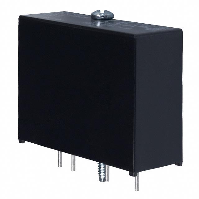
Solid State Relays for Industrial I/O
G3TC
Reliable SSRs for I/O Module Mounting
Boards
• Use I/O SSRs as an interface between logic circuitry and the
load.
• Variety of AC/DC input and output modules with industrystandard footprint and color coding.
• Built-in hold down screw fastens relay to board to eliminate
loosening by vabration.
• Optical Isolation - Dielectric strength of 4 kV between input
and output terminals.
• Zero cross function on AC output models.
• AC and DC input versions incorporate a rectifier to accept
both AC or DC inputs.
• UL, CSA and TUV approved; marked with CE.
Ordering Information
■ Input Module
Function
Color
AC input
Isolation
Yellow
Photo-coupler
Input operating
voltage range
90-140 VDC/AC
180-280 VDC/AC
DC input
White
10-32 VDC/AC
Logic level output
supply voltage
Model
5 VDC
G3TC-IAC5 AC/DC120
15 VDC
G3TC-IAC15 AC/DC120
24 VDC
G3TC-IAC24 AC/DC120
5 VDC
G3TC-IAC5A AC/DC120
15 VDC
G3TC-IAC15A AC/DC120
24 VDC
G3TC-IAC24A AC/DC120
5 VDC
G3TC-IDC5 DC/AC24
15 VDC
G3TC-IDC15 DC/AC24
24 VDC
G3TC-IDC24 DC/AC24
■ Output Module
Function
AC output
Color
Black
Isolation
Photo-triac
Rated input
voltage
5 VDC
15 VDC
Rated output voltage
(Applicable output voltage)
3 A at 120 VAC
(3 A at 75-140 VAC)
24 VDC
5 VDC
15 VDC
Red
Photo-coupler
5 VDC
15 VDC
15 VDC
24 VDC
1
Solid State Relay
G3TC
G3TC-OAC15 DC15
G3TC-OAC5A DC5
G3TC-OAC15A DC15
G3TC-OAC24A DC24
3 A at 60 VDC
(3 A at 5-60 VDC)
24 VDC
5 VDC
G3TC-OAC5 DC5
G3TC-OAC24 DC24
3 A at 240 VAC
(3 A at 75-280 VAC)
24 VDC
DC output
Model
G3TC-ODC5 DC5
G3TC-ODC15 DC15
G3TC-ODC24 DC24
1 A at 200 VDC
(1 A at 5-200 VDC)
G3TC-ODC5 DC5
G3TC-ODC15 DC15
G3TC-ODC24 DC24
�■ Typical Applications
• HVAC, refrigeration equipment
• Automation controls
• Injection molding machines
• Packaging equipment
■ I/O Classification by Color
AC equipment
90 to 140 VAC/DC
180 to 280 VAC/DC
G3TC-IAC5 AC/DC120
G3TC-IAC15 AC/DC120
G3TC-IAC24 AC/DC120
Yellow
5 to 24 VDC
White
5 to 24 VDC
AC input module
DC equipment
10 to 32 VDC/AC
G3TC-IDC5 DC/AC24
G3TC-IDC15 DC/AC24
G3TC-IDC24 DC/AC24
DC Input module
AC equipment
75 to 140 VAC, 3 A
75 to 280 VAC, 3 A
G3TC-OAC5 DC5
G3TC-OAC15 DC15
G3TC-OAC24 DC24
PC or
logic
circuitry
Black
G3TC-OAC5A DC5
G3TC-OAC15A DC15
G3TC-OAC24A DC24
5 to 24 VDC
AC output module
DC equipment
5 to 60 VDC, 3 A;
5 to 200 VDC, 1 A
G3TC-ODC5 DC5
G3TC-ODC15 DC15
G3TC-ODC24 DC24
Red
G3TC-ODC5A DC5
G3TC-ODC15A DC15
G3TC-ODC24A DC24
5 to 24 VDC
DC output module
Specifications
■ Common Characteristics
Insulation resistance
100 MΩ min at 500 VDC
Dielectric strength
4000 VAC, 50/60 Hz for 1 minute between input and output
Vibration resistance
Malfunction: 10 to 55 Hz, 1.5 mm double amplitude
Shock resistance
Malfunction: 1,000 m/s2
Ambient temperature
Operating: -30°C to 80°C with no icing or condensation
Storage: -30°C to 100°C with no icing or condensation
Ambient humidity
Operating: 45% to 85%
Approved standards
UL508, UL60950, CSA22.2 No 14, No 950, EN60950
Solid State Relay
G3TC
2
�■ AC Input Module G3TC-IAC
Ratings (Ambient Temperature 25°C)
Input
Item
G3TC-IAC5
G3TC-IAC15
G3TC-IAC24
G3TC-IAC5A
G3TC-IAC15A
Rated voltage
120 VAC/DC
240 VAC/DC
Operating voltage
90-140 VAC/DC
180-280 VAC/DC
Must operate voltage
90 VAC/DC max.
180 VAC/DC max.
Must release voltage
25 VAC/DC min.
45 VAC/DC min.
Input current at rated voltage
5 mA max.
5 mA max.
Input resistance (see note 1)
30k Ω
69k Ω
G3TC-IAC24A
Output
Item
G3TC-IAC5
G3TC-IAC15
G3TC-IAC24
G3TC-IAC5A
G3TC-IAC15A
G3TC-IAC24A
Output supply voltage-nominal
5 VDC
15 VDC
24 VDC
5 VDC
15 VDC
24 VDC
Output supply voltage-range
4.5-6 VDC
12-18 VDC
20-30 VDC
4.5-6 VDC
12-18 VDC
20-30 VDC
Output supply current at rated
input voltage (see note 2)
12 mA max.
15 mA max.
18 mA max.
12 mA max.
15 mA max.
18 mA max.
Control resistance (Rc in circuit
configuration - see note 1)
240 Ω
1k Ω
2.2k Ω
240 Ω
1k Ω
2.2k Ω
Output current
50 mA max.
Characteristics
Item
G3TC-IAC5
Operate time (see note 3)
20 ms max.
Release time (see note 3)
20 ms max.
Output ON voltage drop
0.4 V max.
Leakage current
100 µA max.
Weight
Approx. 40g
G3TC-IAC15
G3TC-IAC24
G3TC-IAC5A
G3TC-IAC15A
G3TC-IAC24A
Note: 1. Resistance values are reference.
2. The input module supplies the current on I/O circuit board at nominal ouput voltage.
3. At nominal output supply voltage, rated input voltage and 25°C.
■ DC Input Module G3TC-IDC
Ratings (Ambient Temperature 25°C)
Input
Item
G3TC-IDC5
Rated voltage
24 VDC/AC
Operating voltage
10-32 VDC/ 15-32 VAC
Must operate voltage
10 VDC/15 VAC max.
Must release voltage
3 VDC/ 3 VAC min.
Input current rated voltage
25 mA max.
Input resistance
1.5k Ω
G3TC-IDC15
G3TC-IDC24
Output
Item
G3TC-IDC5
G3TC-IDC15
G3TC-IDC24
Output supply voltage-nominal
5 VDC
15 VDC
Output supply voltage-range
4.5-6 VDC
12-18 VDC
20-30 VDC
Output supply current at rated input voltage (see note 2)
12 mA max.
15 mA max.
18 mA max.
1k Ω
2.2k Ω
Control resistance (Rc in circuit configuration - see note 1) 240 Ω
Output current
3
Solid State Relay G3TC
50 mA max.
24 VDC
�Characteristics
Item
G3TC-IDC5
Operate time (see note 3)
5 ms max.
Release time (see note 3)
5 ms max.
Output ON voltage drop
0.4 V max.
Leakage current
100 µA max.
Weight
Approx. 40g
G3TC-IDC15
G3TC-IDC24
Note: 1. Resistance values are reference.
2. The input module supplies the current on I/O circuit board at nominal ouput voltage.
3. At nominal output supply voltage, rated input voltage and 25°C.
■ AC Output Module G3TC-OAC
Ratings (Ambient Temperature 25°C)
Input
Item
G3TC-OAC5
G3TC-OAC15
15 VDC
G3TC-OAC24
5 VDC
G3TC-OAC15A
15 VDC
G3TC-OAC24A
5 VDC
Operating voltage
2.5-8 VDC
9-16 VDC
18-32 VDC
2.5-8 VDC
9-16 VDC
18-32 VDC
Must operate
voltage
2.5 VDC max.
9 VDC max.
18 VDC max.
2.5 VDC max.
9 VDC max.
18 VDC max.
Must release
voltage
1 VDC min.
Input current at rated
voltage (see note 1)
18 mA max.
1k Ω
2.2k Ω
240 Ω
1k Ω
2.2k Ω
Control resistance (Rc 240 Ω
in circuit configuration - see note 2)
24 VDC
G3TC-OAC5A
Rated voltage
24 VDC
Output
Item
G3TC-OAC5
G3TC-OAC15
G3TC-OAC24
G3TC-OAC5A
Rated load voltage
120 VAC
240 VAC
Load voltage range
75-140 VAC
75-280 VAC
Load current
0.05 to 3 A
Inrush current
45 A (60 Hz, 1 cycle)
G3TC-OAC15A
G3TC-OAC24A
Characteristics
Item
G3TC-OAC5
G3TC-OAC15
G3TC-OAC24
Operate time (see note 3)
1/2 of load power source cycle + 1 ms max.
Release time (see note 3)
1/2 of load power source cycle + 1 ms max.
Output ON voltage drop
1.6 V (RMS) max.
Leakage current
2.5 mA max. (at 120 VAC)
Weight
Approx. 45g
G3TC-OAC5A
G3TC-OAC15A
G3TC-OAC24A
5 mA max. (at 240 VAC)
Note: 1. Resistance values are reference.
2. The input module supplies the current on I/O circuit board at nominal ouput voltage.
3. At nominal output supply voltage, rated input voltage and 25°C.
Solid State Relay
G3TC
4
�■ DC Output Module G3TC-ODC
Ratings (Ambient Temperature 25°C)
Input
Item
G3TC-ODC5
G3TC-ODC15
Rated voltage
5 VDC
15 VDC
Operating voltage
2.5-8 VDC
Must operate
voltage
2.5 VDC max.
Must release
voltage
1 VDC min.
Input current at rated
voltage (see note 1)
18 mA max.
Control resistance (Rc 240 Ω
in circuit configuration - see note 2)
G3TC-ODC24
G3TC-ODC5A
G3TC-ODC15A
G3TC-ODC24A
24 VDC
5 VDC
15 VDC
24 VDC
9-16 VDC
18-32 VDC
2.5-8 VDC
9-16 VDC
18-32 VDC
9 VDC max.
18 VDC max.
2.5 VDC max.
9 VDC max.
18 VDC max.
1k Ω
2.2k Ω
240 Ω
1k Ω
2.2k Ω
Output
Item
G3TC-ODC5
G3TC-ODC15
G3TC-ODC24
G3TC-ODC5A
Rated load voltage
60 VDC
200 VDC
Load voltage range
5-60 VDC
5-200 VDC
Load current
0.01 to 3 A
0.01 to 1.0 A
Inrush current
18 A (10 ms)
9 A (10 ms)
G3TC-ODC15A
G3TC-ODC24A
Characteristics
Item
G3TC-ODC5
G3TC-ODC15
G3TC-ODC24
G3TC-ODC5A
G3TC-ODC15A
Operate time (see note 3)
50 µs max.
100 µs max.
Release time (see note 3)
50 µs max. (see note 4)
750 µs max.
Output ON voltage drop
1.6 V (RMS)max.
Leakage current
1 mA max. (at 60 VAC)
1 mA max. (at 200 VAC)
Weight
Approx. 45g
Approx. 40g
Note: 1.
2.
3.
4.
5
The output module supplies the current on I/O circuit board at nominal input voltage.
Resistance values are reference.
At rated load voltage, maximum rated load current, rated input voltage and 25°C.
At 24 VDC load voltage, 3 A load current and 25°C.
Solid State Relay G3TC
G3TC-ODC24A
�Engineering Data
■ Internal Circuit
G3TC-IAC/IDC
G3TC-OAC
Note: Internal biasing circuitry is different between AC input and DC
input modules
G3TC-ODC
Solid State Relay
G3TC
6
�■ Load Current vs. Ambient Temperature Characteristics
G3TC-OAC5, -OAC15, -OAC24,
-OAC5A, -OAC15A, -OAC24A
G3TC-ODC5, -ODC15, -ODC24
G3TC-ODC5A, -ODC15A, -ODC24A
■ Inrush Current Resitivity
Non-repetitive (Keep inrush current to half the rated value if it occurs.)
G3TC-OAC5, -OAC15, -OAC24,
-OAC5A, -OAC15A, -OAC24A
7
G3TC-ODC5, -ODC15, -ODC24
Solid State Relay G3TC
G3TC-ODC5A, -ODC15A, -ODC24A
�Dimensions
Unit: mm (inch)
Note: AC and DC input versions only; pin
5 is not present on output modules.
■ Approvals
UL (File No. E64562)/CSA (File No. 35535)
Input
Output
Model
Input voltage
Model
Load voltage Load current
G3TC-IAC5, -IAC15, -IAC24
90-140 V AC/DC
G3TC-IAC5, -IAC15, -IAC24
5/15/24 VDC
G3TC-IAC5A, -IAC15A, -IAC24A
180-280 V AC/DC
G3TC-IAC5A, -IAC15A, -IAC24A
5/15/24 VDC
50 mA
G3TC-IDC5, -IDC15, -IDC24
10-32 VDC, 12-32 VAC
G3TC-IDC5, -IDC15, -IDC24
5/15/24 VDC
50 mA
G3TC-ODC5, -ODC5A, -OAC5, -OAC5A
5 VDC
G3TC-ODC5, -ODC15, -ODC24
5-60 VDC
G3TC-ODC15, -ODC15A, -OAC15, -OAC15A 15 VDC
G3TC-ODC5A, -ODC15A, -ODC24A 5-200 VDC
G3TC-ODC24, -ODC24A, -OAC24, -OAC24A 24 VDC
G3TC-OAC5, -OAC15, -OAC24
50 mA
3A
1A
75-140 VAC
3A
G3TC-OAC5A, -OAC15A, -OAC24A 75-280 VAC
3A
Note: The rated values approved by each of the safety standards (e.g., UL, CSA and TUV) may be different from the performance characteristics
individually defined in this catalog.
Solid State Relay
G3TC
8
�Precautions
!WARNING
Do not touch the relay while power is supplied or immediately after
G3TC is turned OFF. Doing so may result in burns.
!WARNING
9. For a DC inductive load, a diode should be connected in parallel
with the load to absorb the counter electromotive force of the
load.
10.For an I/O mounting rack that is installed horizontally, use the
G3TC with loads that are within the following conditions.
G3TC-OAC5, -OAC5A, -OAC15, -OAC15A, -OAC24, -OAC24A
Do not touch the load terminal of the G3TC immediately after the
power is turned OFF, otherwise an electric shock may be received
due to the residual charge of the built-in C/R circuit.
4
!WARNING
3
Be sure to turn OFF the power supply to the G3TC before wiring,
otherwise an electric shock may result.
Ensure that a short-circuit current does not flow on the load side of
the SSR, otherwise the G3TC may be damaged.
2.1
Load current (A)
!WARNING
2
1
0.64
■ General Precautions
1. Do not apply excessive voltage or current to the input or output
circuit of the G3TC. Doing so may result in malfunction or burning.
2. Do not connect the input and output circuits incorrectly. Doing so
may result in malfunction or burning.
3. Do not obstruct the flow of air around the G3TC. Abnormal heating of the G3TC may result in short-circuiting of output elements
and burning.
■ Correct Use
Before Actual Operation
1. In actual operation, the G3TC may cause accidents that were
unforeseeable at the theoretical stage. Therefore, it is necessary
to test the G3TC under a variety of conditions that are possible.
As for the characteristics of the G3TC, it is necessary to consider
the differences between G3TC models.
2. The ratings in this datasheet are for testing in a temperature
range of 15 to 30°C, a relative humidity range of 25% to 85%, and
an atmospheric pressure range of 88 to 106kPa. When testing
operation, it is necessary to confirm correct operation not only
with the actual load that will be used, but also at the same ambient conditions as for actual operation.
3. The input circuitry does not incorporate a circuit protecting the
SSR from being damaged due to a reversed connection. Make
sure that the polarity is correct when connecting the input lines.
4. Only use the G3TC with loads that are within the rated values.
Using the G3TC with loads outside the rated values may result in
malfunction, damage, or burning.
5. Use a power supply within the rated frequency range. Using a
power supply outside the rated frequency range may result in
malfunction, damage, or burning.
6. No over-voltage absorption element is built in. Therefore, if the
G3TC is connected to an inductive load, be sure to connect an
over-voltage absorption element.
7. As protection against accidents due to short-circuiting, be sure to
install protective devices, such as fuses on the power supply side.
8. Keep wiring separate from high-voltage power lines and use wires
of an appropriate length, otherwise malfunction and damage may
result due to induction.
9
Solid State Relay G3TC
0
Ambient temperature (°C)
G3TC-ODC5, -ODC15, -ODC24
4
Horizontal mounting
3
2.7
Load current (A)
At OMRON, we are constantly working to improve the quality and
reliability of our products. SSRs, however, use semiconductors,
which are prone to malfunction. Be sure to use SSRs within their
rated value. Use the SSR only in systems that are designed with
redundancies, flame protection, counter measures to prevent operation errors, and other countermeasures to prevent accidents involving human life or fires.
Horizontal mounting
2
1
0.64
0
Ambient temperature (°C)
�■ Operating and Storage
Environments
Transportation
When transporting the G3TC, observe the following points. Not doing
so may result in damage, malfunction, or deterioration of performance characteristics.
Operating Ambient Temperature
The rated value for the ambient operating temperature of the G3TC
is for when there is no built-up heat. For this, reason, under conditions where heat dissipation is not good due to poor ventilation, and
where heat may build up easily, the actual temperature of the G3TC
may exceed the rated value resulting in malfunction or burning.
When using the G3TC, design the system to allow heat dissipation
sufficient to stay below the Load Current vs. Ambient Temperature
characteristic curve. Note also that the ambient temperature of the
G3TC may increase as a result of environmental conditions (e.g., climate, air-conditioning) and operating conditions (e.g., mounting in an
airtight panel).
1. Do not drop the G3TC or subject it to severe vibrations or shock.
2. Do not transport the product if it is wet.
Vibration and Shock
Do not subject the SSR to excessive vibration or shock. Otherwise
the SSR may malfunction and internal components may be damaged.
Operating and Storage Locations
Do not use or store the G3TC in the following locations. Doing so
may result in damage, malfunction, or deterioration of performance
characteristics.
1. Do not use or store in locations subject to direct sunlight.
2. Do not use in locations subject to ambient temperatures outside
the range -30° to 80°C.
3. Do not use in locations subject to relative humidity outside the
range 45% to 85% or locations subject to condensation as the
result of severe change in temperature.
4. Do not store in locations subject to ambient temperatures outside
the range -30° to 100°C.
5. Do not use or store in locations subject to corrosive or flammable
gases.
6. Do not use or store in locations subject to dust (especially iron
dust) or salts.
7. Do not use or store in locations subject to shock or vibration.
8. Do not use or store in locations subject to exposure to water, oil,
or chemicals.
ALL DIMENSIONS SHOWN ARE IN MILLIMETERS. To convert millimeters into inches, divide by 25.4
OMRON ELECTRONICS LLC
OMRON CANADA, INC.
OMRON ON-LINE
One Commerce Drive
Schaumburg, IL 60173
885 Milner Avenue
Toronto, Ontario M1B 5V8
847-882-2288
416-286-6465
Global - http://www.omron.com
USA - http://www.omron.com/oei
Canada - http://www.omron.ca
Cat. No. GCRLY8
01/03
Specifications subject to change without notice
Solid State Relay
Printed in USA
G3TC
10
�